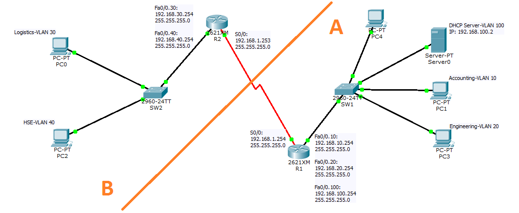
In this article I am going to show how you can implement DHCP relay agent and inter-VLAN routing with OSPF (as shown in Figure. 1). Let’s start with a short description of the scenario and then we will proceed through the step by step configuration guide.

Figure. 1
Scenario:
- A DHCP server in the entire network must assign all the IP addresses that are required.
- We have 5 different VLANs and Subnets named Accounting, Engineering, and Server on SW1 and Logistics & HSE on SW2. Devices that are in these VLANs need to be assigned the IP address automatically by a DHCP server.
- We need inter-VLAN routing for all VLANs.
- Two routers are connecting segment A to B (refer to Figure 1 above) and the ROAS is implemented on both of them.
- Use OSPF routing protocol to route packets between segment A and B.
Procedure:
First let’s create VLANs on SW1 and SW2. Login to the switch and issue the commands below in order to configure VLANs on the switches.
SW1 Configuration:
Create VLANs according to the scenario and assign the ports to the VLANs:
Switch#config t
Switch(config)#hostname SW1
SW1(config)#vlan 10
SW1(config-vlan)#name Accounting
SW1(config-vlan)#vlan 20
SW1(config-vlan)#name Engineering
SW1(config-vlan)#vlan 100
SW1(config-vlan)#name Server
After creating VLANs switchports to the vlans, you need to change the ports to access mode.
SW1(config)#interface fastEthernet 0/1
SW1(config-if)#switchport mode access
SW1(config-if)#switchport access vlan 10
SW1(config)#interface fastEthernet 0/2
SW1(config-if)#switchport mode access
SW1(config-if)#switchport access vlan 20
SW1(config)#interface fastEthernet 0/3
SW1(config-if)#switchport mode access
SW1(config-if)#switchport access vlan 100
SW1(config)#interface fastEthernet 0/23
SW1(config-if)#switchport mode access
SW1(config-if)#switchport access vlan 100
Verify the settings by issuing the Show vlan brief command. The output should look similar to Figure. 2.
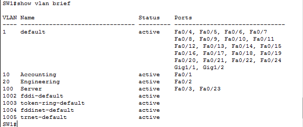
Figure. 2
According to the scenario we need to implement Inter-vlan routing on the SW1. So we must designate a port as Trunk port to enable Inter-vlan routing on it and then we must connect this port to R1.
To make a port trunk port issue these commands in SW1 command line interface.
SW1#config t
SW1(config)#interface fastEthernet 0/24
SW1(config-if)#switchport trunk allowed vlan 10,20,100
SW1(config-if)#switchport mode trunk
Now let’s add the first router to the packet tracer and configure ROAS for Inter-vlan routing. To configure Inter-vlan we must make 4 virtual interfaces on one of the R1’s Fast-Ethernet interfaces. Here I am going to use Fa0/0 to add these virtual interfaces.
Router>en
R1#config t
R1(config)#hostname R1
R1(config)#interface fastEthernet 0/0
R1(config-if)#no shutdown
R1(config-if)#exit
R1(config)#interface fastEthernet 0/0.10
R1(config-subif)#encapsulation dot1Q
R1(config-subif)#ip address 192.168.10.254 255.255.255.0
R1(config-subif)#exit
R1(config)#interface fastEthernet 0/0.20
R1(config-subif)#encapsulation dot1Q
R1(config-subif)#ip address 192.168.20.254 255.255.255.0
R1(config-subif)#exit
R1(config)#interface fastEthernet 0/0.100
R1(config-subif)#encapsulation dot1Q
R1(config-subif)#ip address 192.168.100.254 255.255.255.0
R1(config-subif)#exit
Inter-vlan routing is now functional. It is time to add a DHCP server and configure the server to lease IPs to the clients in segment A.
Click on the server and assign the IP address of the server on Desktop tab as depicted in Figure. 3.
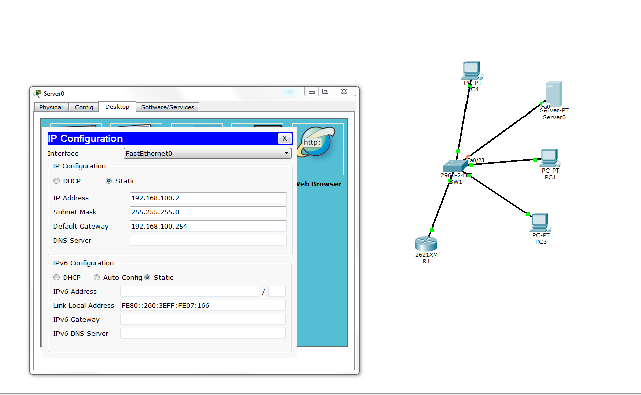
Figure. 3
To configure the DHCP server click on the Config tab and assign the Scopes parameters as shown in Figure. 4.
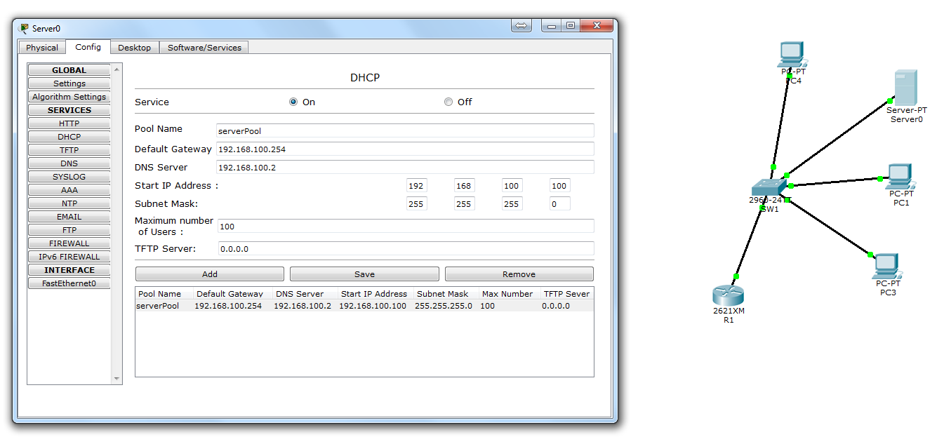
Figure. 4
To test if the configuration is working or not click on the PC4 and set the IP configuration settings to DHCP. In Figure.5 you can see that PC4 has obtained its IP lease from the server.
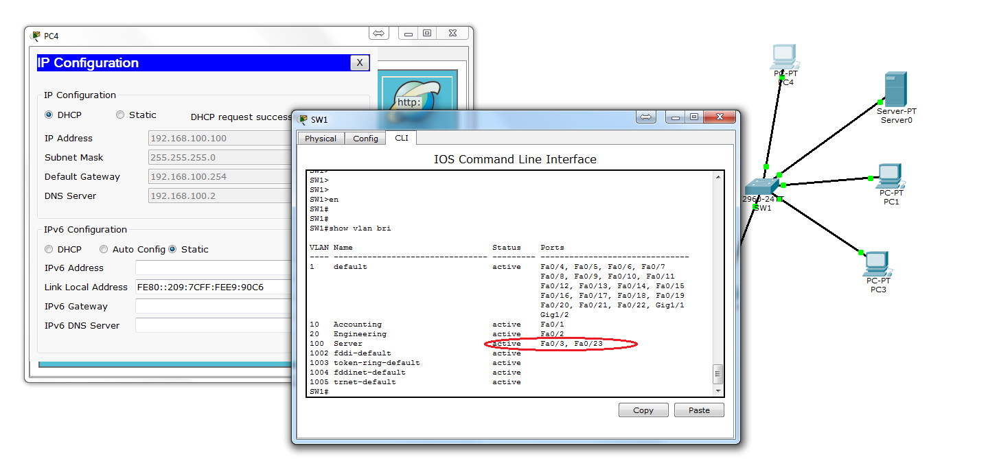
Figure. 5
To read the rest of the Article, go to How To Implement DHCP – Part 2